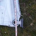
1 Here's a pic of my engine compartment, shortly after the installation of the new wiring harness. Part of the project was a quick clean of the entire area, as it was covered in a thin layer of black .. soot? I thought it was soot; it was fine, black and in the area of a diesel engine. What else could it be? Inside the blue circle is some of the blackness, not yet cleaned. In the blue rectangle is some teak and oak that just didn't want to get clean. But I could not figure out where it was coming from! There was no exhaust leak, nothing coming out of the intake, no smoke when running, nothing. I considered carbon dust from the alternator brushes, but there was far too much blackness for that to seem likely, and in places that just didn't seem possible. And there was something else a bit odd; the "soot" didn't get a guy as dirty as I thought it should, my hands washing up just fine. So where was the "soot" coming from? Google to the rescue, and the discovery of a number of posts about belts being chewed up and spewing rubber dust. A close examination of the pulleys showed this to be very likely, as the next frame will show, so off they came. |
 2 Here's the pulley off the raw water pump. The closeup at the bottom shows something that looks more like a wood rasp than a precision mechanical part! |
 3 This is one half of the two part alternator pulley. Not quite as bad as the water pump, but again, hardly what one would expect. |
 4 The pulleys were mounted in a lathe on some homemade mandrels and spun at about 2000 RPM. Initial cleaning was with medium grit emery paper (lightly held) followed by some fine paper followed by some steel wool. Here's all the pulleys after some good cleanup. Well, not quite ALL the pulleys; the main pulley on the crank was NEVER EVER EVER EVER coming off, and I tried HARD, building a custom puller just for the job. I suspect this part has a tapered shaft, which tends grab REALLY well, and is almost certainly made of a different metal than the crank, the two resulting in something chemically welded together. This pulley will be cleaned in place as best I can. Unfortunately, the story does not end here ... |
 5 Removing the pulley off the water pump revealed a WHOLE lotta rust, so much that the next decision .. cross my fingers and hope or do something about it .. was an easy one. SOMETHING had to be done. |
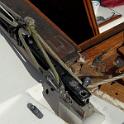
 6 An examination of the Yanmar parts manual showed that the pump was a VERY simple device, and looked easily rebuildable. This was confimed by the fact that Yanmar actually produced a rebuild kit! So, rebuild it is. First, !! remove the snag ring on the pulley side !! Then after removing the back plate and the impeller, remove the shaft. This CAN be tapped out with a hammer, but a press is the preferred method. Here I've got the pump stacked up on my little hydraulic press. Note that I'm using a piece of brass between the pulley shaft and the HARD steel bar of the press. This is to protect the shaft from "mushrooming". |
 7 Here's the shaft removed. The red arrow points to a hidden snap ring between the two bearings. That means the bearings have to be removed in the direction of the green arrows. On my pump, the bearings were only a gentle interference fit and came off reasonably easily. I made a couple of wedges of 16 gauge steel, filing to shape, placed them on either side and squeezed in a vice. The bearings moved easily. The process was repeated a couple of times with additional metal acting as spacers. Upon examination, the bearings were completely standard 6202ZZ type, readily available elsewhere. As these were a significant part of the cost of the rebuild kit, and as the kit contained other parts almost certainly not required, I decided to buy just the few pieces I needed individually. |
 8 Here's two views of the pump body. I gave it a good cleaning, solvent initially, then dishwashing liquid, but did not use anything abrasive. |
 9 Here's some tools made up on my lathe. Left to right, we have a bearing insert tool to press against the outer race, another to press against the inner race, a seal insert tool and two "gauges". With the pump still assembled, I made these gauges to show me precisely where the bearings sat in relation to the end of the shaft. You'll see this a couple of pictures from now. |
 10 Here's the "oil seal", which is in fact the water seal, and is another very standard part. The manufacturer is NOK, part number is AE0478A. This is a TC type seal, dual lip, 28mm OD, 13 mm ID, 7 mm thick. At my bearing supply house, it's about a dollar from another manufacturer. It's the "other manufacturer" that concerns me. These seals have a wound spring on the inside to keep tension on the shaft. I was astonished to find that the spring in the stock seal was still perfectly shiny. While everything else was rusty as could be, this spring looked new. I therefore had to assume that it was made out of stainless steel (NOK does not describe the material used to make this spring). Every other manufacturer that listed the spring material simply said "carbon steel", which implied to me that it would rust. Also, a couple of people had reported using an O ring here in place of the spring because of the rust worries. Add these two things up and I opted for the Yanmar part, at $15.00! |
 11 Here's the seal installed, with the inset showing the tool. The tool was aluminum, so it souldn't scratch the housing, and a VERY nice fit in the bore. This ensured that that seal would go in straight; in my experience, this is the second most likely reason for seals to leak; bad installation. |
 12 Here's the first bearing pressed onto the shaft. If you look hard, you can see the snap ring, installed before the bearing went on. The keen eyed will notice that the bearings have a rubber seal, making them 6202RS2 type bearings. While this type of bearing is not rated for as high an RPM as the stock 6202ZZ bearings with metal shields, a close examination of the specs showed they should be just fine at the RPMs this pump will run at. More importantly, if the front seal does start to leak again, the rubber could provide a bit of protection. The inset shows the gauge in use, to set the bearing location on the shaft. You'll also note the shaft is quite a bit shinier than in previous pics. It too saw time in the lathe with some steel wool. Thankfully, there was only a small score in the shaft in the area of the seal, and a 30 seconds with steel wool removed the mark without appreciably thinning the shaft. |
 13 Two more pieces to buy, the bearing cover and a rubber washer. I suppose I could have reused the old cover, but this part was only a couple of dollars, so I decided to treat myself to a new one. The rubber washer is described as a water thrower. Apparently, if any water does leak through the "oil seal", this spinning bit of rubber will throw it out the holes in the side of the pump body. |
 14 First bearing installed, using the tool to press on the outer race. |
 15 Second bearing installed, and also the outer snap ring. Deciding which tool to use here was trickier; do I press on the inner race or the outer? Tirns out that the first bearing went into the bore VERY easily, almost finger pressure, so I elected to press this secind bearing onto the shaft the same way as the first, on the inner race. |
 16 Here's the second gauge in use. The inset shows that I'm within about 5 thou; well close enough. |
 17 Next step was to install the "cam"; the brass bit that actually does the work of pumping. The cam is held in place with a brass screw, that broke with just the gentlest of pressure. I elected to use a stainless steel replacement, taking care to use suitable goop to pretect the dissimilar metals. I also noted upon disassembly that there was a THIN film of what looked like silicon seal between the cam and the pump body. I added some as well, the key being THIN. Note quite sure of why this was there .. perhaps as a seal, perhaps to hold the cam in place if the screw is ever removed to drain. |
 18 Last step. My cover plate was seriously scored. On the left we see black marks; they are actually recesses, not easily photographed, but surprisingly deep. Maybe some sand got in between the impeller and plate somewhere along the line. So out to the belt sander, starting at 50 grit and running up to 320. After almost 30 minutes of sanding (and several burns on my fingers from the hot metal THROUGH MY WELDING GLOVES), the plate was pretty flat again. Then it was onto a glass plate with some 400 and then 600 grit wet and dry for a final polish. The image on the right is the result; you can see the reflection of the fastener drawers. I'm happy. |